A Verkle tree is a commitment framework that operates similarly to a Merkle tree, yet has significantly smaller witnesses. It functions by substituting the hashes in a Merkle tree with a vector commitment, rendering broader branching factors more effective.
Gratitude to Kevaundray Wedderburn for the insights regarding the post.
Overview
Refer to the following for information on how verkle trees function:
The purpose of this post is to elucidate the specific configuration of the draft verkle tree EIP. It targets client developers seeking to implement verkle trees and looking for a primer before exploring the EIP in greater detail.
Verkle trees bring forth a variety of modifications to the tree architecture. The most notable alterations are:
- a transition from 20-byte keys to 32-byte keys (not to be confused with 32-byte addresses, which constitutes a different modification);
- the amalgamation of the account and storage tries; and ultimately
- the arrival of the verkle trie itself, which employs vector commitments in lieu of hashes.
For the vector commitment mechanism used in the verkle tree, we utilize Pedersen commitments. Pedersen commitments rely on elliptic curves. For an introduction to Pedersen commitments and their application as polynomial or vector commitments utilizing Inner Product Arguments, refer to here.
The curve we are implementing is Bandersnatch. This curve was selected due to its performance, as well as for its capability to facilitate efficient SNARKs in BLS12_381 to reason about the verkle tree in the future. This could prove beneficial for rollups and also allow an enhancement where all witnesses can be condensed into a single SNARK once that becomes feasible, without the necessity of another commitment update.
The curve order/scalar field size of Bandersnatch is p = 13108968793781547619861935127046491459309155893440570251786403306729687672801, which is a 253-bit prime number. Consequently, we can only safely commit to bit strings of up to 252 bits, else the field will overflow. We opted for a branching factor (width) of 256 for the verkle tree, meaning each commitment can commit to a maximum of 256 values of 252 bits each (or more accurately, integers up to p – 1). We express this as Commit(v₀, v₁, …, v₂₅₅) to commit to the array v of length 256.
Layout of the verkle tree
A primary design objective of the verkle tree EIP is to make access to nearby positions (e.g., storage with nearly identical addresses or adjacent code segments) inexpensive. To achieve this, a key comprises a stem of 31 bytes and a suffix of one byte, culminating in a total of 32 bytes. The key strategy is devised so that “proximate” storage locations are linked to the same stem with distinct suffixes. For further information, please consult the EIP draft.
The verkle tree itself is ultimately comprised of two categories of nodes:
- Extension nodes, which symbolize 256 values sharing the same stem but differing suffixes
- Inner nodes, which can accommodate up to 256 children, comprised of either other inner nodes or extension nodes.
The commitment to an extension node is a commitment to a 4 element vector; the remaining positions will be 0. It is:
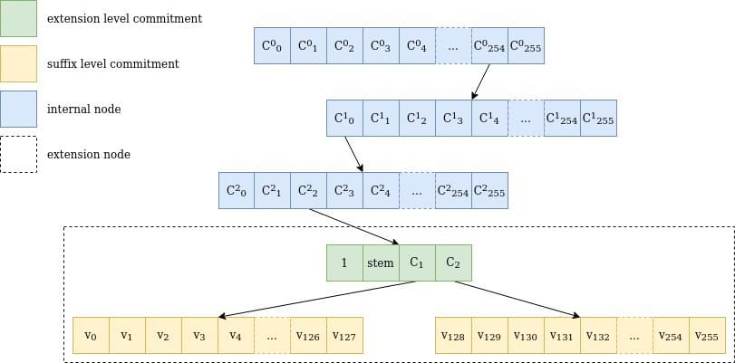
C₁ and C₂ are two additional commitments that secure all values with a stem equivalent to stem. The rationale for requiring two commitments is that values encompass 32 bytes, but we can only hold 252 bits in one field element. A single commitment would therefore be insufficient to store 256 values. Thus, C₁ retains the values for suffix 0 to 127, while C₂ encompasses 128 to 255, with the values divided in two to fit within the field size (we’ll discuss this later).
The extension, together with the commitments C₁ and C₂, is known as the “extension-and-suffix tree” (EaS for brevity).

Figure 1 Illustration of a path through a verkle tree for the key 0xfe0002abcd..ff04: the route traverses 3 internal nodes with 256 children each (254, 0, 2), a single extension node representing abcd..ff, and the two suffix tree commitments, including the value for 04, v₄. It is important to note that stem is actually the first 31 bytes of the key, including the path through the internal nodes.
Commitment to the values leaf nodes
Each extension and suffix tree node encapsulates 256 values. Given that a value is 256 bits wide, and we can only safely accommodate 252 bits in a single field element, four bits would be forfeited if we merely attempted to store one value in one field element.
To address this issue, we decided to divide the cluster of 256 values into two sets of 128 values each. Each 32-byte value within a set is partitioned into two 16-byte values. Hence, a value vᵢ∈ 𝔹₃₂ transforms into v⁽ˡᵒʷᵉʳ⁾ᵢ ∈ 𝔹₁₆ and v⁽ᵘᵖᵖᵉʳ⁾ᵢ∈ 𝔹₁₆ such that v⁽ˡᵒʷᵉʳ⁾ᵢ ++ v⁽ᵘᵖᵖᵉʳ⁾ᵢ= vᵢ.
A “leaf marker” is appended to the v⁽ˡᵒʷᵉʳ⁾ᵢ, to distinguish between a leaf that has never been accessed and a leaf that has been overwritten with zeros. No value is ever removed from a verkle tree. This is essential for forthcoming state expiry frameworks. That marker is established at the 129th bit, i.e., v⁽ˡᵒʷᵉʳ ᵐᵒᵈⁱᶠⁱᵉᵈ⁾ᵢ = v⁽ˡᵒʷᵉʳ⁾ᵢ + 2¹²⁸ if vᵢ has been accessed prior, and v⁽ˡᵒʷᵉʳ ᵐᵒᵈⁱᶠⁱᵉᵈ⁾ᵢ= 0 if vᵢ has not been accessed before.
The two obligations C₁ and C₂ are then characterized as

Commitment of extension nodes
The commitment to an extension node consists of an “extension indicator”, which is simply the numeral 1, the two subtree commitments C₁ and C₂, along with the stem of the key that leads to this extension node.

In contrast to extension nodes in the Merkle-Patricia tree, which only include the segment of the key that connects the parent internal node to the child internal node, the stem incorporates the entire key up to that moment. This is because verkle trees are created with stateless proofs in consideration: if a new key is added that “splits” the extension into two, the older sibling does not need to be revised, facilitating a more compact proof.
Commitment of Internal nodes
Internal nodes feature a more straightforward calculation approach for their commitments: the node is perceived as a vector of 256 values, representing the (field rendition of the) root commitment of each of their 256 subtrees. The commitment for an empty subtree is 0. Should the subtree not be void, then the commitment for the internal node is

where the Cᵢ denote the offspring of the internal node, and 0 if an offspring is absent.
Insertion into the tree
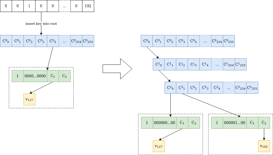
Figure 2 is an example of the procedure for inserting a new value into the tree, which becomes intriguing when the stems intersect at multiple initial bytes.

Figure 2 Value v₁₉₂ is added at location 0000010000…0000 in a verkle tree that holds only value v₁₂₇ at location 0000000000…0000. As the stems vary at the third byte, two internal nodes are appended until the differing byte. Following this, another “extension-and-suffix” tree is added, which includes a complete 31-byte stem. The initial node remains unaltered, and C²₀ retains the same value as C⁰₀ prior to the addition.
Shallower trees, smaller proofs
The verkle tree architecture enables shallower trees, leading to a reduction in the volume of stored data. Its real strength, however, lies in the capability to generate smaller proofs, i.e., witnesses. This will be elaborated in the subsequent article.

